
Driveshaft Phasing Marks Matter When a Slip Joint Is Separated
Driveshaft Phasing Marks Matter When a Slip Joint Is Separated
When a driveshaft slip joint is separated, its original relative yoke phase must be preserved according to the applicable shaft and vehicle service information. Spline engagement alone does not prove that the slip member…
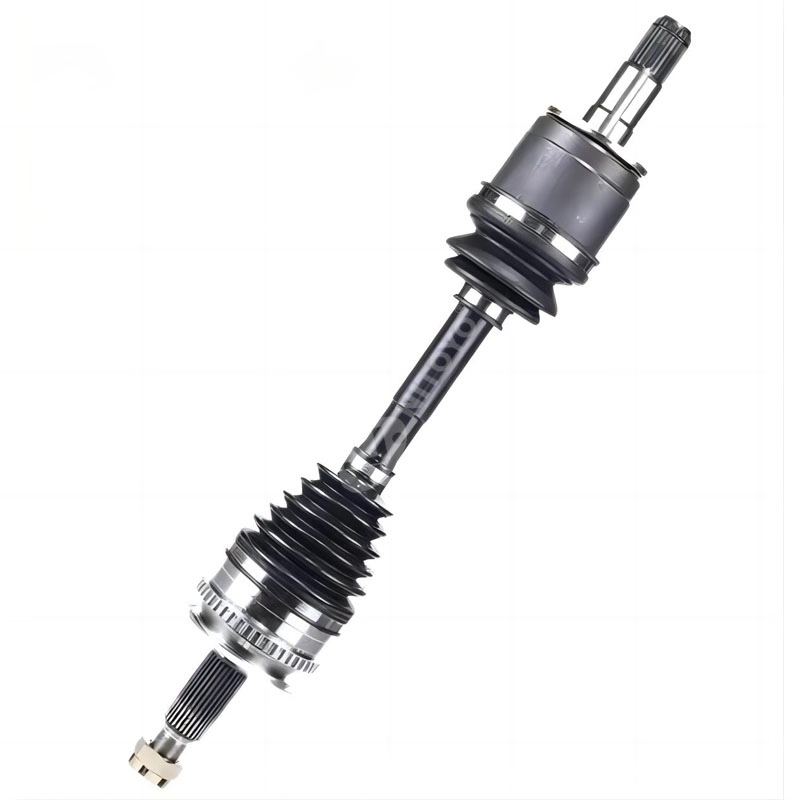
When a driveshaft slip joint is separated, its original relative yoke phase must be preserved according to the applicable shaft and vehicle service information. Spline engagement alone does not prove that the slip member has been reassembled in its original orientation.
This matters because a driveline reassembled out of phase can vibrate and can contribute to failure of driveline and attaching components. Before separation, record the shaft type, existing phasing marks, slip-spline or master-spline arrangement, balance marks, center-bearing configuration, and applicable service-manual reference.
Part of the Driveshafts, CV Joints and Wheel Hubs Guides.
A Slip Joint Can Reassemble in More Than One Position
A slip joint allows the driveshaft assembly to change effective length as the drivetrain and suspension move. Its splined components may appear to slide together normally after service, even if their relative rotational position has changed.
That is why spline engagement is not the final check. The relevant question is whether the shaft has been returned to the orientation specified for that exact driveshaft assembly.
A master spline may limit how parts engage, but it should not be assumed to establish the original assembly position unless the applicable manufacturer documentation states that it does. Likewise, a visible yoke shape, tube diameter, grease fitting position, or spline count does not independently prove correct phasing.
For supported Spicer Life Series applications, Dana’s service manual warns that reassembly out of the original phase can cause vibration and failure of the driveline and attaching components. The manual also directs service personnel to mark mating driveshaft components before disassembly where required by the procedure.
Record the Shaft Before It Is Separated
The most useful time to establish assembly identity is before the slip member, shaft sections, or related connections are disturbed. One clear record is more useful than relying on memory, a generic illustration, or a similar shaft on another vehicle.
A completed record does not replace the correct service procedure. It creates a traceable basis for confirming that the shaft being reassembled is the same shaft configuration that was documented before separation.
What the Fields Actually Prove
Shaft Type
The shaft type establishes the general arrangement of the driveline. A one-piece shaft, a two-piece shaft with a center bearing, and a shaft with a coupling section can have different identification points, service steps, and phasing dependencies.
It does not prove that another shaft with the same number of tubes, joints, or flanges uses the same service arrangement.
Phasing Marks
Phasing marks document the original relationship between mating shaft components. They are evidence of the assembly position that existed before disassembly.
A paint mark, scribe line, or stamped mark should be interpreted in context. It may be a factory mark, a previous service mark, a balance-related mark, or an unrelated marking. If its meaning cannot be confirmed, do not treat it as definitive proof of the correct orientation.
Slip Spline or Master Spline
A slip spline permits axial movement. A master spline, where present, can limit the number of possible assembly positions. However, the presence of an indexing feature does not establish that the remaining alignment conditions are correct for every shaft design.
The applicable shaft documentation must determine whether the feature is the intended phasing control, an assembly aid, or only one part of the required reassembly procedure.
Balance Marks
Balance weights and balance-related marks concern the rotating assembly. They should not be removed, relocated, or assumed to indicate phase without the relevant manufacturer documentation.
A driveshaft can contain both phase-related reference marks and balancing features. They are not interchangeable labels.
Center Bearing
A center bearing identifies a multi-piece driveline arrangement and can affect how individual shaft sections are handled and reinstalled. Its bracket, support, and alignment requirements are vehicle-specific.
A center bearing location alone does not establish the correct relationship between all yokes and shaft sections. Use the exact service information for the complete driveline configuration.
A Wrong-Match Scenario: The Splines Engage, but the Shaft Is Not Verified
A technician separates the slip member during service and later finds that the splines slide back together in several positions. The yokes appear similar from a distance, and the shaft length seems normal after reassembly.
That is not enough to confirm correct phasing.
The original paint marks may have been cleaned away. The shaft may have a master spline that narrows the engagement options without proving the specified yoke relationship. A nearby balance mark may be mistaken for a phasing mark. If the vehicle has a center bearing, one shaft section may also be incorrectly oriented relative to the next section.
In this situation, do not select an orientation based on visual similarity or spline engagement alone. Pause the reassembly and obtain the service documentation for the exact vehicle and shaft configuration. If the original reference position cannot be established, the issue is not a routine catalog lookup; it is an assembly-identity question that requires qualified driveline evaluation.
When Exact Service Information Is Required
Exact service information is required whenever the work moves beyond documenting visible marks and identifying a candidate component. This includes:
-
Removing or reinstalling a driveshaft from the vehicle.
-
Separating a slip member, coupling shaft, or multiple driveshaft sections.
-
Replacing a universal joint, yoke, flange, center bearing, slip member, or related hardware.
-
Determining whether bolts, straps, retainers, washers, or nuts are reusable.
-
Establishing torque values, fastening sequence, or component orientation.
-
Evaluating vibration, runout, balance, looseness, damaged tubing, or related driveline concerns.
-
Confirming whether a balance mark, master spline, or existing paint mark is part of the required assembly method.
For the Dana Spicer Life Series covered by its service manual, the manufacturer warns against reusing certain attachment hardware and directs users to follow required specifications. Those instructions apply only to the documented product family and procedure; they should not be transferred to another vehicle or driveshaft design.
Driveshaft work can involve heavy rotating components and safety-critical attachment hardware. Do not work beneath an unsupported vehicle. Use the vehicle-maker or component-maker procedure for vehicle support, shaft handling, fastening hardware, and final inspection.
Turn the Inspection Into a Usable Parts Request
A replacement or sourcing request should preserve both the part identity and the assembly information. Asking for a “driveshaft” or “slip yoke” without those records can produce a visually similar but unsuitable component.
Related articles
 Exhaust Manifold Gasket Orientation: When the Metallic Face MattersKnowledge
 Exhaust Clamps: Choose for the Pipe Joint, Not Diameter AloneKnowledge
 Brake Light Switch Replacement: Check the Adjuster Design Before Handling ItKnowledge
 Fuel Line Hose: Fuel Resistance Does Not Prove Injection-System SuitabilityKnowledge

